Cleans reeds effectively by means of ultrasound at appropriate temperature settings.
Number of passes with the ultrasonic oscillator can be easily adjusted for enhanced cleaning
efficiency.
Pump circulation of water between the heating unit and washing basin makes for efficient use of heat
energy.
As is well known in the art, the reed 16 is a comb-like device which spaces the warp yarn 20 in the
desired order and also places each succeeding filling thread against that already woven. The reed
usually consists of a top and bottom rib 22 of metal into which flat metal blades or wires 24 are set.
The space between two adjacent wires is called a dent and the count or fineness of the reed is
calculated by the number of dents per inch. The warp 20 is drawn through the dents and the sizing
and/or finish in the yarn tends to accumulate in the dents. This accumulation is especially bad in
the area below the weft tunnel 26 in the reed.
When it is desired to clean the size, finish and/or lint from the dents in the reed, the ultra-sonic
reed cleaner is best suitable to clean .The size and number of ultra-sonic components on the
ultra-sonic cleaner depends primarily on the width & length of the reed to be cleaned.
ULTRASONIC GENERATORS WITH TRANSDUCERS
| Ultrasonic Generator |
Digital Ultrasonic Generator, Mosfet-Based, Microprocessor controlled with built in digital read out of frequency & output Current. 28 numbers of generators having output of 1500 watts each encased in a single frame fitted with control panel.
Power control possible
Installation in climate control cabinet
It is possible to switch ultrasonic in groups or in total 100% |
| Ultrasonic Transducer (Submersible Type) |
Encased inside Stainless Steel-316 Box, hermetically sealed |
| Number of Ultrasonic Transducers Boxes |
14Number X 3000 Watts each (Changeable) |
| Combined Ultrasonic Power |
42 Kilo Watts |
| Ultrasonic Transducer Box Mounting |
Side Wall Mounting in the tank (No.5 in figure below) |
| Number of Transducer Boxes in Each side of the wall |
7 Nos. of transducers of 3000 watts each, mounted on the two side walls of the tank |
| Material of construction of transducer box |
Stainless Steel 316 grade, 3 MM Thick, radiating surface coated with hard chrome plating for extended life. |
| Frequency of Ultrasonic Generator |
28 +/- 3 Khz |
| Heaters |
48 Kilo Watts (8 x 6 Nos. Ceramic Heaters SS tube 316 Ti casing) – Changeable with Full bath |
What is Ultrasonic Cleaner & How does it Work?
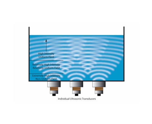
An Ultrasonic Cleaner comprises of a tank (with different sizes), motor/ circuit for cleaning the contaminated parts, a removable basket / tray. To begin the cleaning process, the cleaning tank is filled with warm water or a cleaning solution. Cleaning solutions can consist of non-ionic surfactants & detergents.. You can then place the components in a basket and place that basket inside the tank.
When you switch on the machine, ultrasound waves and chemicals combined to create bubbles that "cling" to the foreign particles such as dirt, oil, and unknown substances. The high frequency waves are sent out and pull the contaminants off of the object. The vibrating motion of the ultrasonic waves creates tiny bubbles in the water known as
cavitation; millions of these bubbles rubs against each-other and into the object resting in the cleaning tank. This cavitation process gently knocks dirt & stain off the object. The motion is very effective at penetrating the tiny crevices which is not possible via human hand or by dunking the instrument in water/ chemical alone.
The Ultrasonic Cleaning Cycle time is approximately 3-5 Minutes depending upon the quantity of objects placed in the basket as well as the level of contamination of the same. Once you set the timer, the machine does its work in few minutes and the dirt now rests in the bottom of the tank. The cavitation effect blasts the particles off the instrument’s surface and leaves them in the solution. You can now remove the basket along with the Instruments and clean them with a dry soft cloth.
Ultrasonic Cleaning system Design
Considerations in the design of any cleaning system include the contaminants on the part(s), the required cleanliness level, the geometry and material of the part(s), the quantity to be processed, and the previous system design and layout (if applicable). The part geometry, production rate, and cleaning time required will determine the size of the cleaning system, once the overall process has been decided. Typical tanks range from 20 to 400 L (5 to 1000 gal), and some are even larger. Other factors that need to be considered are cleaning solutions and temperatures, rinsing (with or without ultrasonics), drying, automation, and load requirements. Our engineers will assist in these decisions and will offer laboratory services and technical expertise.
Cleanliness Considerations
In a typical aqueous ultrasonic cleaning system, it is the cleaning stage(s) that will remove or loosen the contaminants. The following rinse stage(s) remove any remaining loosened soils and residual detergent, and a dryer removes any remaining rinse water. The overall process of the system is usually determined experimentally. We have an applications lab where, through a process of experience, trial, and error, a properly designed cleaning process can be determined to meet the cleanliness levels specified.There are a variety of ways to check for cleanliness. Some are as simple as a water break test on the part to see if most oil has been removed. Others are as elaborate as surface quality monitoring that uses optically stimulated electron emission technology to measure thin films of contaminants down to the Angstrom level.
Part Handling
The geometry of the parts is carefully analyzed to determine how it will be placed in the cleaning tank. Large parts, such as engine blocks, can be suspended directly from a hoist, whereas smaller parts will usually be placed in a basket. The most important factor in parts placement is to be sure that air is not trapped anywhere inside the part. If an air pocket is allowed to form, such as in a blind hole that would be facing downward toward the bottom of the tank, the cleaning solution and effects of cavitations will not be able to reach this particular area. The part will have to be rotated somehow in the tank during the cleaning process to allow the cleaning solution to reach the area where air was previously trapped. This can be accomplished either manually, by the attending operator, or by a rotating arm on an automated lift mechanism.
It is best if small parts can be physically separated when placed in a basket. An example would be to place machined valve bodies in a basket with some type of divider or locator for each one. Many times, however, in high output lines it is not possible to separate parts physically, such as in the manufacture of electrical connector pins where thousands of parts may need to be cleaned at one time because of the high production output and the small size. Ultrasonic agitation will be able to reach between these parts and allow the solution's scrubbing power to remove the contaminants, even if the parts are stacked on top of one another. On the other hand, rinse water may not remove all of the residual detergent; it becomes difficult for the dryer to remove moisture from embedded parts. The problem is easily solved by having an automated hoist with a constant rotating fixture on the arm that allows the basket to tumble at 1 to 3 rpm. This rotation allows the parts to tumble slowly and exposes the embedded pieces for proper rinsing and drying.